To Control the process
Introducing the PAPP International Electronic Controller as
designed by John Rohner, created by Tom Rohner and Programmed by:
Tom Miller, John and Tom Rohner.
for the 198x PAPP designed Version of a
Plasmic Transition Process Engine
John Rohner's Electronic Controller for the Papp International Running engine as Certified.
=========================================================
Plasmic
Control Groups Electronic Control System - electronic controller
System Overall Block Diagram. for
OUR "Patent applied for" Plasmic
Engine Control System (ECS):
=========================================================
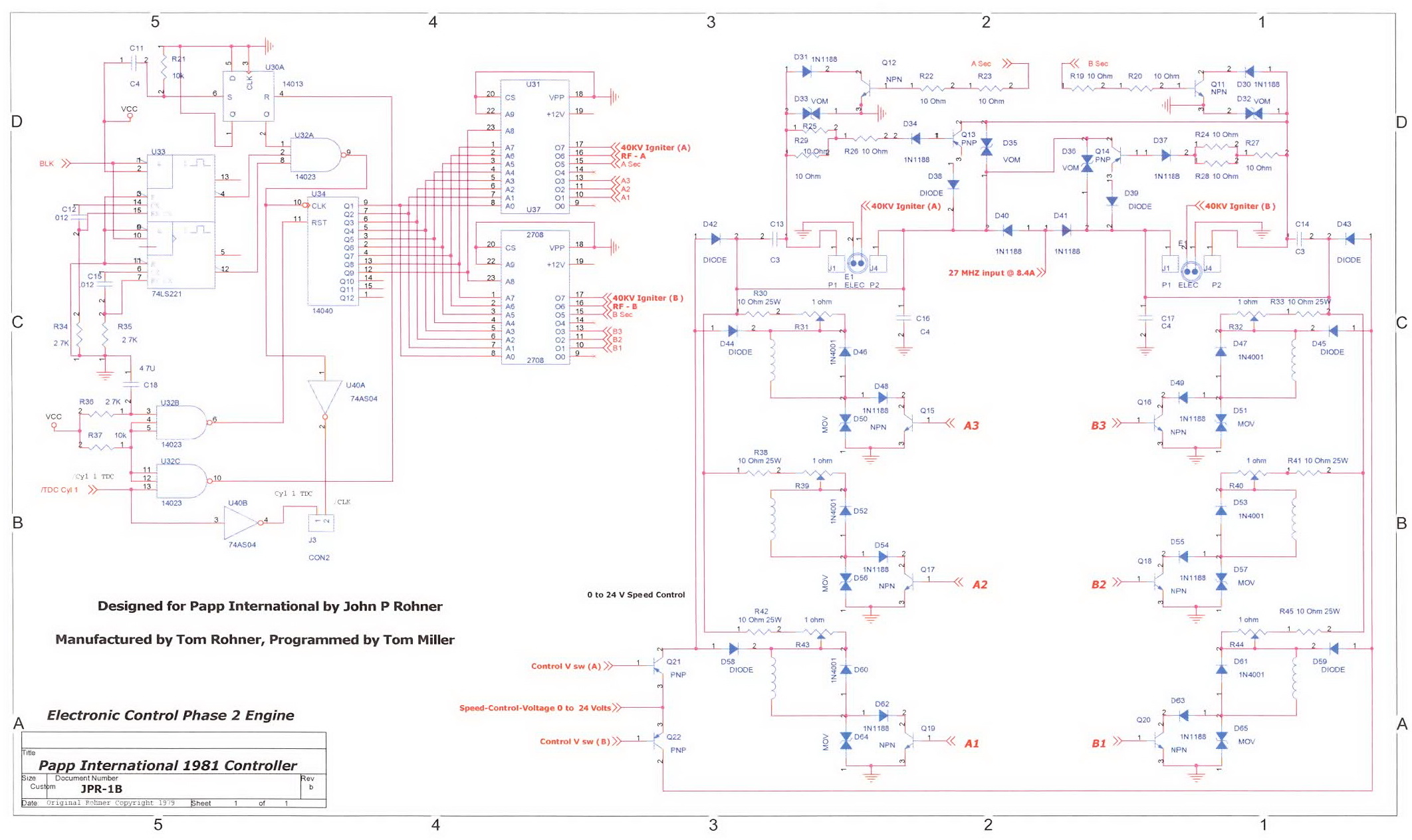
Figure 1. The Papp International 1982 Control System, as copyright by John Rohner, the designer of same..
|
|
|
Please notice:
My Brother Tom and his tech, Tom Miller, are both dead now.
This presentation is a testament to their working with me, to get the Papp International engine
running and certified to prove the technology was valid.
They were GOOD people.
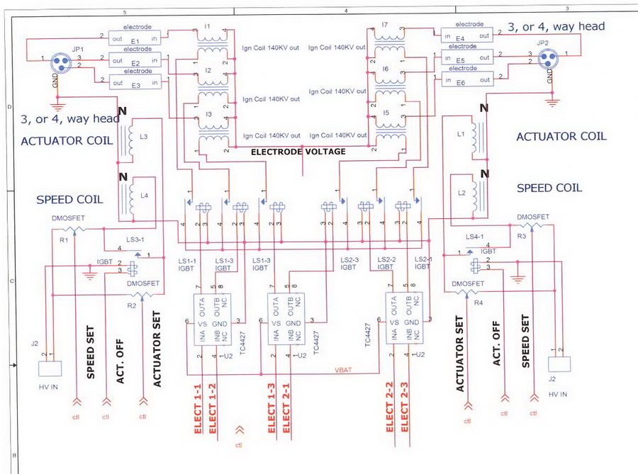
In this 1982 Electronic Motor Control (Figure 1 above) a single signal is provided at top dead center (TDC) of the cylinder 1 piston by the crankshaft position sensor. This synchronizes the multi-vibrator that pulses the input to the binary counter at a frequency which is divided to create a binary number that addresses the read-only memories, and which switch on a signal, or signals, to drive the coils, igniter, speed or run voltages and all others based on a specific programmed one time fixed timing as required for this piston's cycle. Operational parameters are static, pre programmed into the PROMs memory, so they are not flexible to motor operational requirements.
As you can see, the PROMs are connected to various switched points on each of the two cylinders.
The timing is strictly relative to degrees of rotation of the crank as related to the cylinder 1 piston position in the operational cycle.
The switching table, to create the proper sequencing, is programmed for each cylinder's operation into that cylinder's programmable read-only memory. PROM 3 is for Cylinder 1 and PROM 2, with all value 180 degrees out of phase, is for Cylinder 2 and show affects all the electrical changes needed to make the engine work and keep the signals synchronized with the positional data.
This schematic is a fully electronic Control system as John Rohner created it based on the Papp original schematic, using UJTs and inoperable as specifications were supplied by Papp way back in the 1970s timeframe, along with pictures, videos and discussion with persons who were familiar with it.
Rohner presents this is as an adequately close approximation to the electronic control for the 1982 Papp Motor that was certified and that Plasmic Transition Process has historical videos of running. available to everyone Rohner has checked, simulated and this schematic could probably work.
However, Papp used two variations, one was a three Cylinder coil system and the other was a four coil system. The three coil system was the certified engine, as is this schematic.
The four coil system was supposed to pass electrons to the other cylinder to create a "perpetual motion" machine. As far as Rohner knows this never worked and in simulation looks to be counter productive to power generation overall.
===========================================================
Here is simple timing Table for information, good enough for a start.
Do remember that the Papp International Engine was limited to 900 RPM, specifically.
CYLINDER 1 SHOWN -- CYLINDER 2 is 180 DEGREES OFFSET..
|
Above is how the actual Papp International 1982 Electronic Control System
as Designed by John Rohner, Built by Tom Rohner
and programmed by Tom Miller
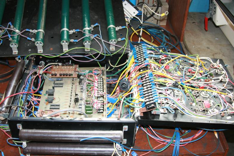
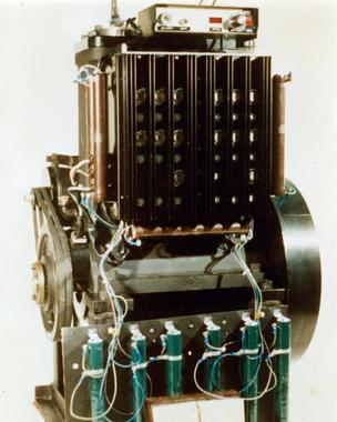
To the right is the controller as it looked mounted
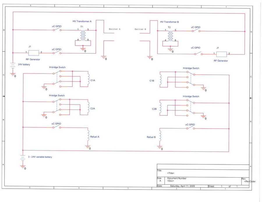
Below is a more modern version of a more complete controller
on the Papp International Engine
See the Schematic for how complex it was >>------------------------------>
using a rheostat and such. This was limited to 900 RPM
as that was what Joe Papp Told John Rohner would be the maximum
engine speed needed to be.
Radio Frequency was generated by a CB set set to channel 3.
that could do everything needed, was completely programmable,
flexible and was not limited in speed. It also generated it's own RF energies.
and was capable of controlling starting, refuel and several "safety systems".
This was used on first PlasmERG running engine.