To Control the process
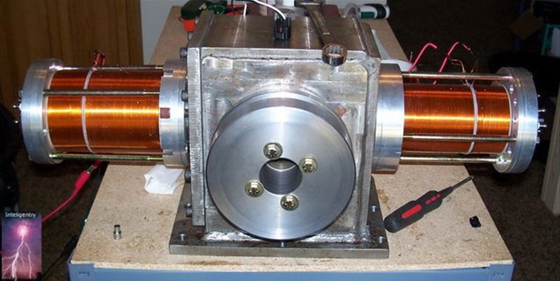
Introducing the "ORIGINAL" PlasmERG Electronic Controller System
for the Plasmic Transition Process Engine.
The Electronic Control System (ECS) used for the Phase 2 running PlasmERG engine.
============================
Plasmic Transition Development Group
and Control Systems Consulting, internationally
Copyrighted and newly Patent Pending
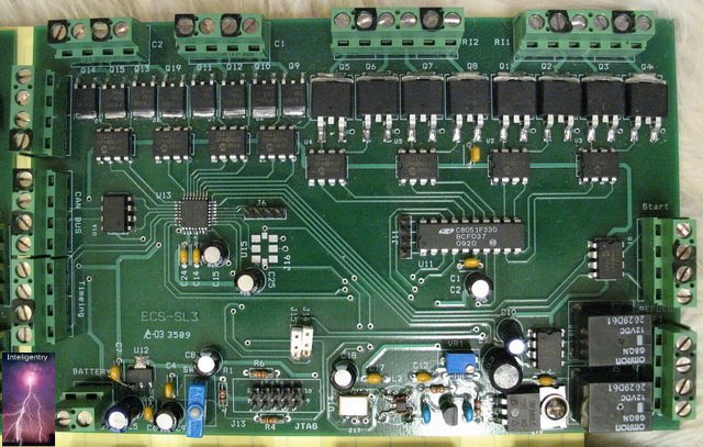
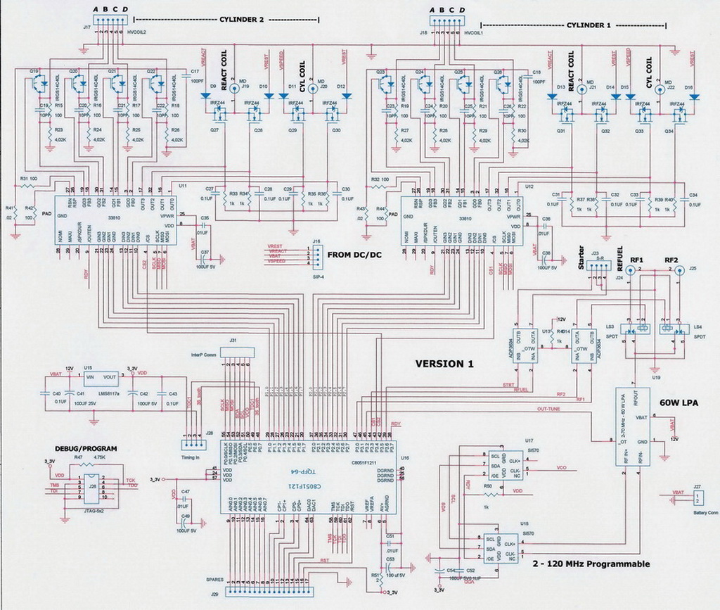
Electronic Control System (ECS)- electronic
controller System Overall Block Diagram. for a
Plasmic Transition Control System :
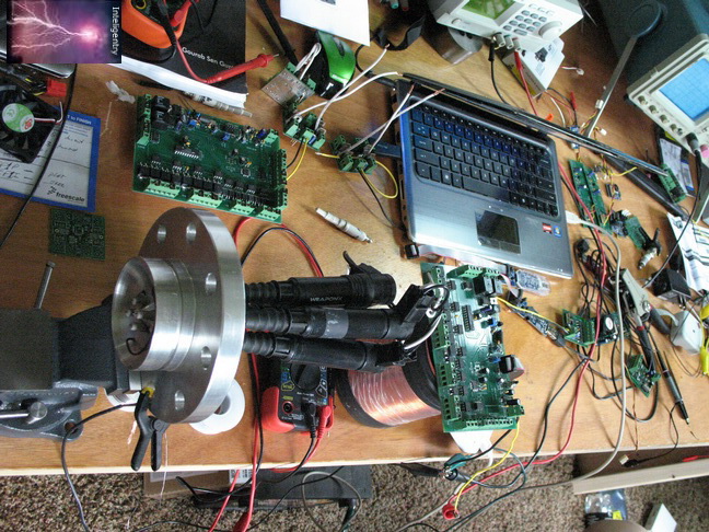
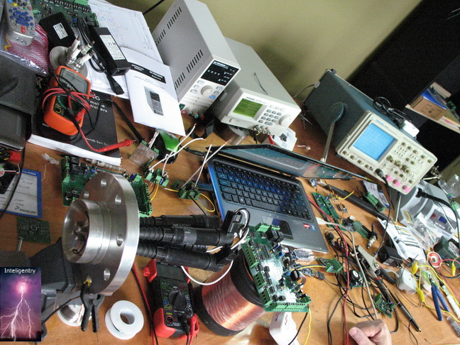
Taking what was learned by building and running
the PlasmERG (Iowa) Engine and what was needed to
accomplish that control system and to stretch
the very basic Papp International Control system, also
designed by John Rohner, resulted in a multiple
"embedded" Microprocessor single board controller
with all the basic elements on board.
This new board had all the coil voltage changes,
Timing input synchronization (to <1 degree),
RF frequency changes, RF Power Output Amplification,
RF switching, Electrode switching, Safety integration,
Plus control of Starter Motor and refuel pulse.
Complete operator control and interface.
The entire control system onto a single
board except for the variable voltage generators.
Best of all it worked and proved all theories.
=============================
The only real problem encountered was that the secondary Microprocessor that synced the electrodes got dropped from production. This had to be designed around and considering that a automotive Temp Range was needed anyway, and the 300 was no where near that it actually saved us time.
We picked up some smarts by replacing this part and that was going to be important later in the development cycle.
=======================================================================
Lets clear the air about a rumor!!!
There is some confusion being created and passed around by a nameless party, it
seems, about the progression of OUR controllers. We did not, in any way, duplicate anything
like the old 1982 John Rohner designed thing that made the old Papp International "Papp" engine work.
The first and simplest control circuit, that John Rohner designed,
was a modern technology mimic of the old Papp International "Certified" motor controller,
that John designed. It was based on his notes, drawings and a his timing MAP, also
presented in Papp Patents, as he corrected it. It was very simple, but.....
John did "simulate" his Ancient control circuit to verify it
met the published data about timings, would work within the constraints reported and
would perform within the very limited confines of operation as shown in the HISTORICAL videos.
BUT this Antique Controller design was
never meant to be used, as is very restrictive, cumbersome and inflexible.
But, STILL much better than Mechanical and Relay types.
Also, the Plasmic Transition Process system, has no need to
reverse coil windings, cross couple capacitors or any of the Mickey Mouse other things
from the Papp patent write up. These may be OK if the target is a
"perpetual motion" dream but useless in reality.
Our early simulations showed that the gains from all this added complexity was miniscule
in both power output or fuel retention and our tests since have proven this is true.
It's a messy thing to do and useless.