To Control the process
Introducing the NEW MODERN Electronic Controller System
for the Plasmic Transition Process Engine
A newly Developed Modern Electronic Control System (ECS).
For use in the Modern Plasmic Transition Process licensed engines.
=========================================================
Plasmic Transition Development Group, (Mexico) and others including RAM Engineering, mx and Control systems consulting (USA) have Control Groups now developing the next Electronic Control System (ECS) that will run the newly manufactured "International versions of the doomed Inteligentry, developed USA, running Type D engine. They also will provide "consulting" for Base or special Electronic Control Systems - electronic controller for new design engines. Then turn over these to the Controller manufacturer in Ireland for manufacturer shipments.
=========================================================
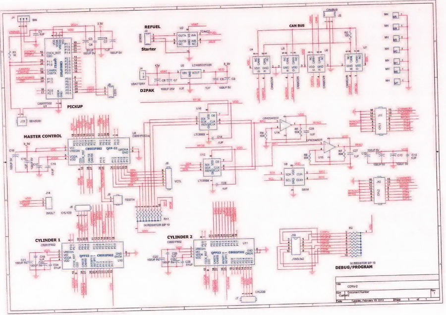
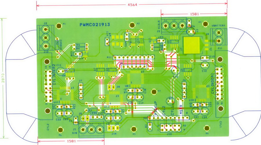
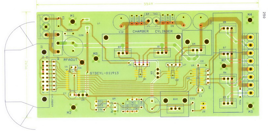
Here's a look at a more modern controller, how to use it and program it.
Pay close attention to the System Overall Block Diagram.
for the BASE Engine Control System (ECS):

=========================================================
Developing and testing a Plasmic Transition Controller
===========================================================
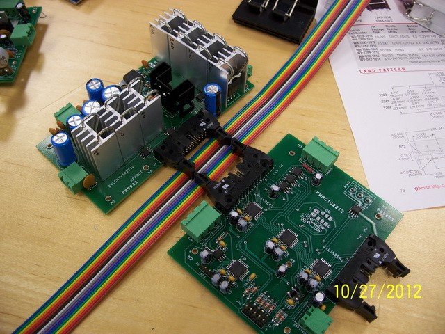
As to Test equipment:
Get a hold of a couple Silicon Labs 502 test boards "ToolStick-F502-DC-UG" daughter boards
Get a couple "ToolStick-F582-DC-UG" Daughter boards
Get 6 "ToolStick-BaseAdapter-UG" connector boards, for connection between the above the computer USB port or UASB extention cable, in the box.
Go To http://www.silabs.com/products/mcu/Pages/8-bit-microcontroller-software.aspx.
Get the full Si Labs 8 bit developers Tool set. Download Silicon Labs 8-bit microcontroller software.
Run this on your programming computer. It will install the SiLabs editor and debugger (IDE)
and a complete version of the Keil Compiler/assembler for compiling C code and assembler.
Remember as you program that small processors in Real time environments need to have all variables located Local.
Do Not Pass Parameters on the stack. remember you can see local variables, in the IDE,
but deciphering the stack is much harder.
Keep It Simple Stupid. (KISS it).
Also moving to store is quicker than load and retrieve from stack.
There is plenty of flash ram available.
That will take care of the pre final component testing environment setup.
also get a couple "ToolStick-Debug-Adapter-UG" daughter boards
Start developing code by first using a 502 Daughter card. It needs to provide a output based on the position of the Variable resistor. See the Freq "sample" programs, from 300 RPM (300/60 = 5 cycles per second) to 3000 RPM (3000/60 = 50 cycles per second)T.
That is the TDC signal input. Pulse width should be equal to about 5 degrees time (T/360*5).
Next set up - a second PWM output at a speed 360 times this pulse.
That now becomes your one degree signal reference for positional count
ie (360*5 = 1800 CPS (1.8 KHz) to 360*50 = 18000 CPS (18 Khz).
Now you have a 1 degree standard stream.
Now you have the required standard two base references needed to program the engine.
This 502 User Board unit now becomes the primary Test Input as it replaces the Engines Reluctor plate and optical Tooth and TDC sensor. Later you will or these into a single stream that has a low period equal to 5 degrees, or one tooth out of the 36 that could be. The Reluctor had 36 teeth of 5 degrees each and 36 opens of 5 degrees and the number 1 tooth is missing. So at TDC you have a low signal for 15 degrees since a tooth is a one and a void is a zero.
This also provides the algorithm for decoding this stream so that the base timing processor can provide a stream pair to the master. A pure TDC and a pulse stream at 360x or resolution to 1 degree.
Later this will get changed to 1/4 degree but as a start this is fine. The sensor can only provide one stream the timing processor must interpret that and provide what is needed by the Master. Also the Timing processor determines the speed of the engine in RPM per every 5 degree slot. It is the only place that would know if the engine is speeding up or slowing down, instantly. Thus it will have a up and down output as well as the master would inform it Via Can Bus or SPI of the current frequency wished. That will be talked about later.
You would also need a spectrum analyzer that can see from 130 MHZ to 800 MHZ as that changes with speed as well.
So their is voltage control of the Cylinder coil as the speed of the engine is CONTROLLED by this voltage. Then there is control of the Transition chamber coil voltage separately, This coil has 3 states, Ionize, Run, and off.
In the Engines with Metal pistons and steel bottom ends this voltage at rest would be 5 volts, to keep the reverse voltage pulse generated by the metal piston as it transitions the coil opposed. The latest type "D" Engines do not require this and rest is ~1 V. The D Engine has a Plastic piston that does not present a mass across the Coil. Thus it creates no Back EMF.
It has a better seat and coefficient of friction so it presents less resistance to movement and better power capture.
Because of the fact that it has less mass, the D Engine is 23 lbs lighter than the C engine, it presents less rotational Kinetic resistance to change to speed up or slow down. The C Engine is thus better for fixed speed applications than the D. But until the D engine and its "snap" the engine was not expected to be used in personal vehicles. The D will be easily used in any application that requires quick run up or slow down in engine speed.
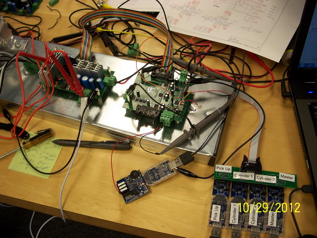
Get a 4 way USB Bridge and plug it into the programmer computer. Plug 4 of the base adapters into the bridge. Each will have it's own ID number. Note each number by writing it on the adapter case for later use. This will allow you to program each microprocessor component individually during tests through the IDE.
Here's some questions answered.
For security reasons, and after having many people try and take the technology for their "personal" enrichment, Rohner has never stated that any running test engine was used.
It was then and remains Rohner's conviction that to show any product before it can be produced
and supplied is "FRAUD". Had the manufacturers actually completed their tasks as expected the engine would have been
show publicly as Rohner had wished, and expected.
But it turns out that before the "Power Gen" show Tana and Dan went to work on the manufacturers
and "convinced" them that they did not need to do their job and create any stock to sell. The failure to have any stock
was what convinced John to NOT run an engine at Power Gen. Pure and simple. The C engine that was at the show
could have been run easily. Mark, Al, Tom and John all knew this. Instead the C & C guys lied all over the place.
BUT, even at that, if the world looked at the published data and believed that, good for them. there was no way to provide that information except from a REAL test, which Rohner did in private.
Fact is, both the C and D engines were tested.
The D engine has many more hours of testing as it had all the mass production advantages, light weight,
very responsive RPM changes, etc.
If the audience would remember the Old Inteligentry web site then you should
remember the definition of the characteristics of the D engine and what these characteristics caused to be
changed in the controller specs and even in John Rohner's expectation.
Primary was from not believing it would work in automobiles easily, because of the run down time, which was very quick in the D. The lack of mass in the piston and crankshaft made it, like any good racing engine, very responsive.
NOW you know why the March 25th meeting was something the SEC/FBI had to stop. Somehow their "surveillance" caught john testing, maybe?. Disruptive Technology Remember?
=========================================================
Questions often asked and answers so you can understand the system
===========================================================
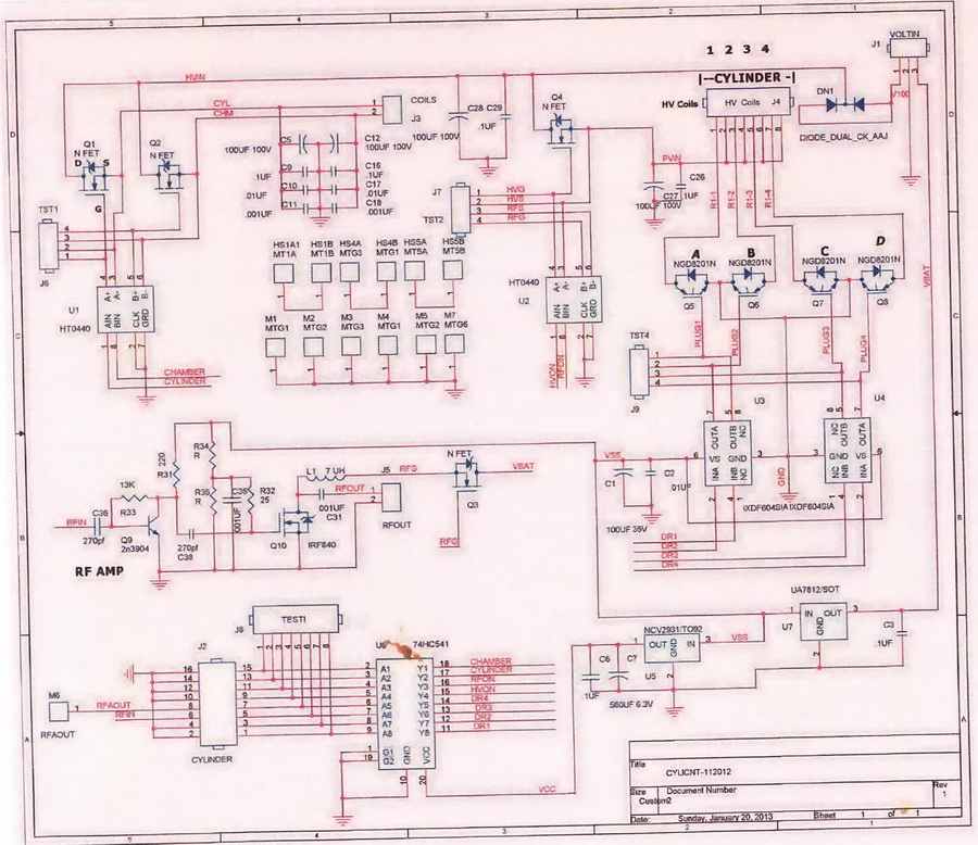
1. Why were HV spark coils reduced from 4 to 3? OK this one from playing with running test engines. It turns out that the C type engine with the aluminum piston had a much heavier mass than the D Type engines plastic piston. So the moment of inertial needed to get it started moving was higher. In the D with the light weight and enhanced lack of resistance this is not so so why not go for Less cost.
2. What is the input voltage to the new coils? The HV Ignition Coils is 24 VDC Base up to 60V max.
3. What is the resting voltage of both the cylinder and reaction chamber coils? 4 to 9 volts DC in the C engine and 1 to 3 VDC in The D. The lack of metal mass transiting the Coil keeps EMF down.
4. What is the maximum voltage of both the cylinder and reaction chamber coils? Control voltage is 30 VDC to 220 VDC at top speed/load on D engine.
5. Operating voltage curves for each coil based verses RPM. Varies up from 3 VDC to 220 VDC on C engine.
6. RF frequency being used verses RPM. Varies from 130MHz to 800 MHz
7. What is used control engine RPM? Voltage on the Cylinder coil for Plasma Squeeze, creating a virtual cylinder for the plasma.
8. Do the timing of events change with RPM, i.e. coil turn on and off times.
YES, curves verses RPM need to be provided for these as well. also remember that there is also a delay time that must be taken into account as well. This will probably be somewhat different from one engine design to another which is why the Consulting company is charged with the initial controller parameters and supplying this critical part. This base table is provided the controller and programmed during testing to provide best results based on engine use specs. In other words if the engine is to be used for electric generation that it needs only be characterized to the generator speed, or speed groups. But if being used in heavy equipment, vehicles etc then The Output power to engine parameters need be adjusted for operation across range. This process is similar to that done with combustion engines to find that "sweet" spot.
The Hardware is useless without proper control. Even loaded with the proper gas mix it still is worthless unless it is properly controlled. Anyone can make a cylinder "Pop" but an engine has to do this repeatedly, reliably, safely and maybe even be able to vary speed.
The gas mix has many different formulas that will work. There is no "magic" there. over 13 variations have already been tested and there are some unusual results. There is no "Magic Mixer" needed.
The Papp International engine, as badly designed as it was, also worked.
Most half assed designs that follow some basic rules will, no matter how clumsy or whatever, work.
The Papp did and it has seals that may be good for a hundred hours and
Papp had to "tinker" with it a bunch.
But with the electronic control (John Rohner designed for it, Tom Rohner built and Tom Miller programmed)
worked and was certified.
Note: this is an ongoing page and any questions you may have can be answered. Soon the new controller schematics and boards will be shown. But as with Inteligentry that will be after they have been proven to do what is needed. VERY SOON!!!
=======================================================================
The Controller would have worked for Jimmy Sabori, and made him wildly successful, also, except it was stripped and hidden when Papp International, and PAPP, got fed up with Robert Rohner and Jimmy was given the contract and not Robert Rohner, 2 years later. Sabori Joined Papp but Robert Rohner had stripped the controller, and hidden it, so Bob could do his "mouse trap" relay thing. History shows clear;y that Robert hid it not wanting Jimmy to have any advantage. Robert then forgot it and when he formed "clean Energy, Inc. (the infamous CEI) he supplied the rat trap and such Evidently forgetting what did work.
The John and Tom Rohner control system, that was used on the "certified" engine, was stripped off and never used again as Robert Rohner replaced it with his version of a relay system that has never worked and will not.
Once they, Robert Rohner and Klosterman, replaced that control the Papp International engine has failed, for over 30 years, except to fill their pockets.
=======================================================================
So the engine "HARDWARE" and the fuel are NOT the key,
as everyone has been told..
The controller is. It is what is flexible enough to get everything to work.
=======================================================================
Maybe Within 5 years we should be able to
replace all coal, petroleum and nuclear power plants with NON polluting, Non
heating upgrades or PERSONAL home systems..
And none of those big noisy ugly windmills either.
Nice quiet VERY Green power.
=========================================================
OUR Developments Are based on our
Innovative designs, knowledge, and Understanding of the
Plasmic Transition Process.
=========================================================